NZ1 front_cover
Publisher: Phill Lavery
Copyright © 2014
All Rights Reserved. No part of this
publication may be reproduced, stored in a retrieval system or
transmitted in any form by any means without prior permission of the
copyright owner. Enquires Should be Made to the Publisher.
Every effort has been made to ensure that this document is free from error or omissions. However, the Publisher, the Author, the Editor or their respective employees or agents, shall not accept responsibility for injury, loss or damage
occasioned to any person acting or refraining from action as a result of material in this document whether or not such injury, loss or damage is in any way due to any negligent act or omission, breach of duty or default on the part of the Publisher, the Author, the Editor or their respective employees or agents.
Photographic content by Phill Lavery.
Author: Phill Lavery
Cover Design: © 2014
Page Design: © 2014
Contents
1 INTRODUCTION
2 SPECIFICATIONS
3 DIMENSIONS
4 The NZ-1 counter
4.1 Reseting the counter
4.2 Cleaning the counter lens
5 ChaNNZ1 front_coverZ1 front_covernging the NZ-1 winding speed
5.1 Setting 1:1 gear ratio
5.2 Setting 1:8 gear ratio
6Using the NZ-1 mounting base
1 INTRODUCTION
The NZ-1 manual Coil Winder is designed to wind medium to large coil
formers such as power transformer or choke coils. It can also be used
to wind air cored radio coils, loud speaker coils and many other
types of inductors. It can be mounted on a table or workbench using
the three mounting hole on it's base.
2 SPECIFICATIONS
Two step gears giving a choice of 1:1 or 1:8 ratio for fast or slow
winding.
Mechanical counter to record each revolution (turn) of the coil winder drive
shaft with a range 0 – 99999 turns
10mm Diameter x 150mm length drive shaft adjustable for many types of
coils
Maximum coil diameter :150mm - maximum coil width:100mm.
Dimensions approx.: (L)350mm x (H)180mm x (W)150mm.
3 DIMENSIONS
NZ-1 Manual coil winder.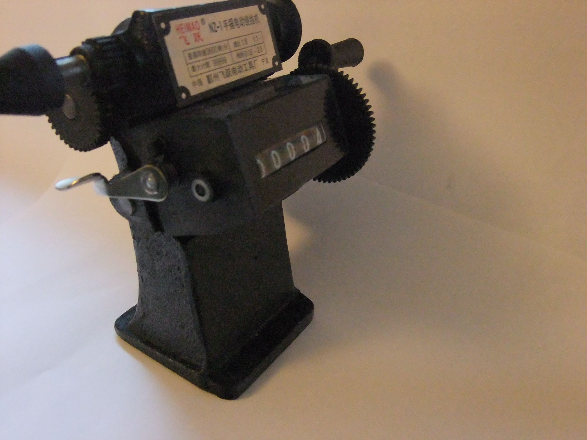
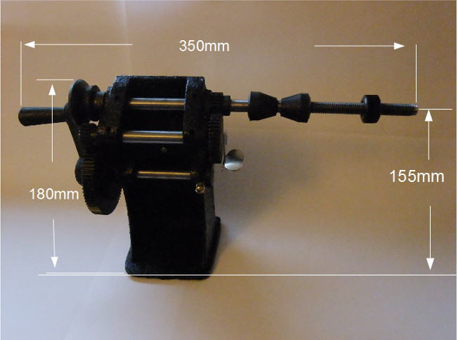
Overall dimensions approx.: (L)350mm x (H)180mm x (W)150mm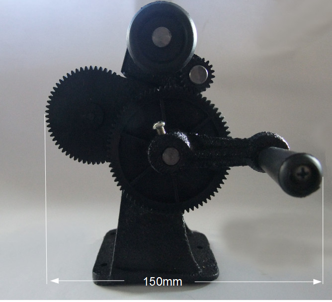
4 The NZ-1 counter
The NZ-1 can count the number of revolutions (turns) of it's drive
shaft. Used to quickly determine the number of coil winding turns of
a coil. The counting range is from 0 – 99999 Turns.
4.1 Reseting the counter
The counter can be set to zero by pushing down on the counter lever –
see photo.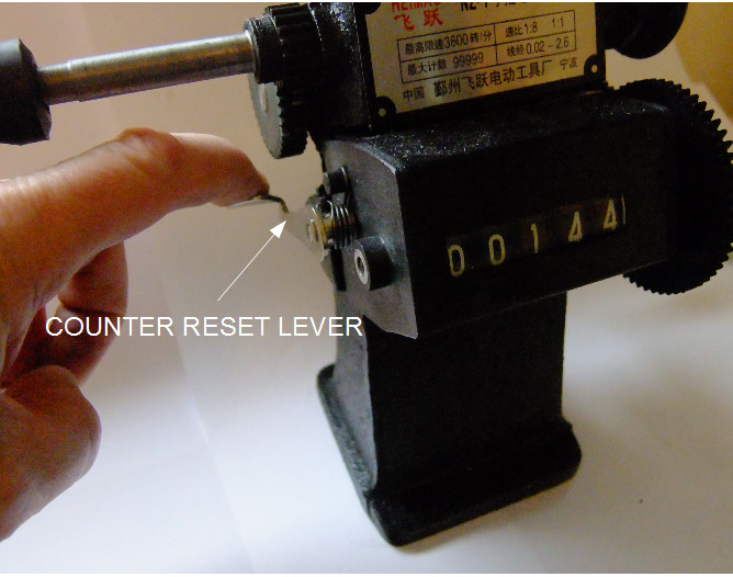
Push the lever down to reset the counter.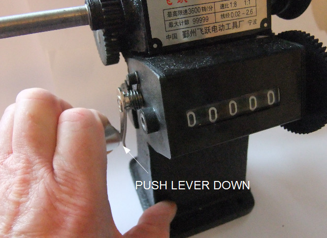
4.2 Cleaning the counter lens
The counter lens may need cleaning if dust or dirt gets into the counter
case. This is easy to do. The counter cover can slide out giving
easy access to the rear or the counter lens.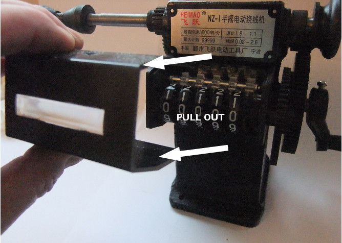
Hold the case at the top & bottom & pull out.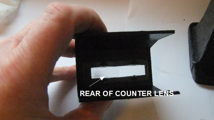
The cover can slide back onto the counter body after cleaning.
5 Changing the NZ-1 winding speed
The NZ-1 manual coil winder has two step gears giving a choice of 1:1
or 1:8 ratio for slow or fast coil winding. When the NZ-1 is set
to 1:1 gear ratio, every complete turn of the winding handle will
result in one revolution of the winding shaft. If the NZ-1 is set to
the 1:8 gear ratio, for every complete turn of the winding handle
will now result in eight revolutions of the winding shaft.
5.1 Setting 1:1 gear ratio
The gear ratio speeds are changed by removing the handle from it's 1:8
drive shaft and fitting it to the 1:1 drive shaft.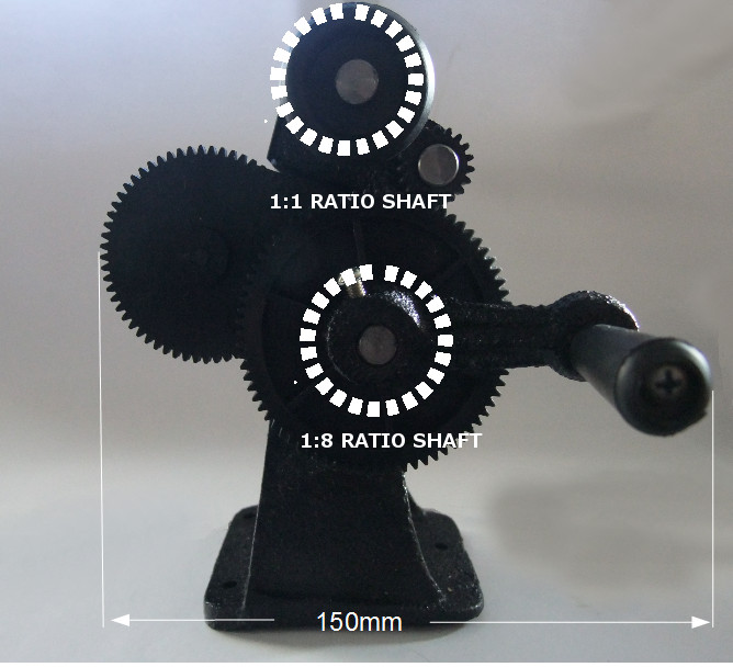
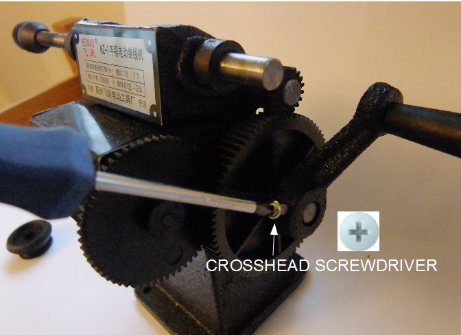
Loosen the locking screw from the handle & slide it off it's shaft.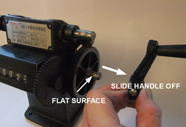
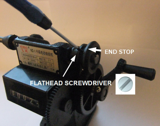
Loosen the locking screw on the end stop.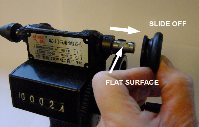
Now the end stop can slide off it's shaft.
Note the flat surface on each of the shafts. When fitting the handle &
end stop, the locking screw must line up with this flat surface to
prevent the handle or end stop slipping on the shaft.
When fitting the handle & end stop, it is important that the handle
has a clearance gap of about 3 mm from the 1:8 shaft & that the
end stop is inserted onto the 1:8 shaft with it's large diameter away
from the end of the shaft. See photo.![]()
![]()
5.2 Setting 1:8 gear ratio
To set the NZ-1 to the 1:8 fast winding, remove the handle from the top
1:1 shaft & the end stop from the lower 1:8 shaft. Place the
handle onto the lower 1:8 shaft & tighten the locking screw
making sure the handle has sufficient clearance to turn freely. Now
place the end stop onto the top 1:1 shaft and tighten the locking
screw. Make sure that the screws line up with the flat surface to
prevent slipping.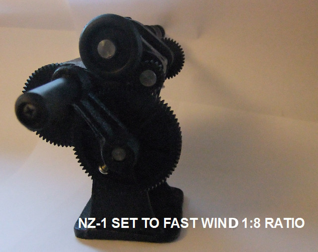
6 Using the NZ-1 mounting base
The NZ-1 has three mounting holes in it's base to facilitate mounting on
a table or workbench or other base.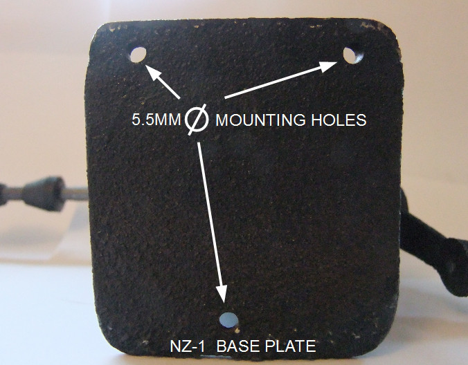
The three mounting holes are 5.5 mm diameter. 5 mm mounting screws will
be suitable.