Special safety tips :
1, A suitable psu adapter should be used with the correct plug polarity connection. Other psu adapter devices, cables or other hardware are prohibited(except for USB cable plug), breach of these conditions may cause damage to the board and is not covered by the warranty.
2, DS18B20 chip is inserted in the socket boards P4, if inserted in the wrong direction, the chip will be damaged, this loss within the scope of the warranty is not covered, please be careful when using! DS18B20 chip must be correctly inserted into the socket of the development board of P4.
The correct direction is that the text of the DS18B20 chip is facing the outer edge of the development board , as shown below. 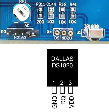
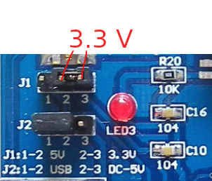
3, When using TFT colour screen ,you must use 3.3V power supply, which should be marked on the development board J1 is marked 3.3 And between the two shorting pins plug link is inserted in the non-labeled J1 base board has two pins 5V and inter Short-circuit the link ,otherwise the TFT colour screen will be damaged . This damage is not covered by the warranty.
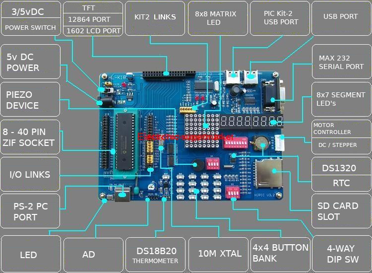
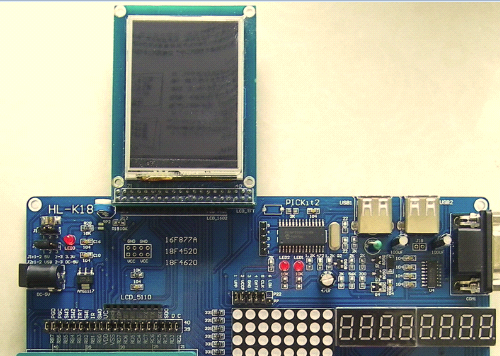
 HL-K18 single - chip experimental development system , is a typical modular, open PIC microcontroller experimental teaching learning system. Each module is provided HL-K18 SCM test development system, mainly the internal PIC microcontroller Feature-based and added some very common peripheral interface devices, in order to fully exhibit the PIC’s unique functional advantages and modular features of this microcontroller.
According to the learning characteristics of the individual,from the practical application of basic skills training and ability to develop products. Also in the use of Microchip’s similar products on the introduction of unique design concepts.
Object-oriented solutions, promote an open,integrated design and type of experimental philosophy, emphasizing with learners as the main body , under the basic structure framework, and leaves room for everyone to fully play with innovative technology.
SCM experimental development system that can adapt to the experimental verification of the basic PIC microcontroller to expand the development of Systematic experiments, provides a versatile experimental platform for everyone to develop applications and innovative design.
Based on this system,various engineering and technical personnel can easily construct various practical application systems, according to the designed circuit,with a simple plug connection, can form a unique and personalized design.
There is no need to make pcb’s,soldering and troubleshooting. Learners can spend more time and energy on system design and software development, greatly improving work efficiency.
Main features of K18 single chip integrated development system.
▲ 1,PICKIT2 online programming simulator with onboard USB interface, can program many types of PIC devices.
The chip machine is programmed online,and hundreds of PIC microcontrollers can be simulated online . The simulator is for beginners and professional developers and can quickly help you find bugs in the program, easily debug the most difficult " program troubleshooting " stages in machine development.
▲ 2, 20 in 1 . K18 development board has one of the largest number of integrated modules for development with 20 integrated Modules,which means learning more content,spending the same money,you will learn more.
In addition,K18 the development board incorporates many of the latest peripheral modules,such as an SD card, PS/2 PC keyboard, AD conversion,dot matrix LED,Photoelectric tachometer,TFT colour screen, USB, etc. , let your learning keep up with with the times!
▲ 3, 100% compatible with "Zero based one week learning PIC microcontroller", " 8 hours to play TFT colour screen",
HuiNet-introduction PIC MCU" and other boutique video tutorials , supporting the " PIC microcontroller C language tutorial" and other illustration tutorials,as well as a large number of data software such as function sets,to help the beginners easily enter into the world of microcontroller programming!
▲ 4, the industry's first support for PIC microcontrollers (100 pins and below PICKIT2 supports hundreds of models),51 MCU needs to buy 51 package (STC company 40 pin and below all models ),AVR single, the latest super professional development of the tablet machine (the AVR microcontroller enhancement package with BOOTLOADER sold at this station).
K18 onboard resources
▲ 1, PS/2 PC keyboard port: connected to a PC standard keyboard.
▲ 2, USB programming, USB emulation : PICKIT2 online programming emulator with onboard USB interface,includes hundreds of PIC microcontrollers for in-circuit programming and simulation, especially their simulation,can help beginners and Professional developers quickly find errors in the program and easily tackle the most difficult " proDifferent kinds of PIC microcontrollers.gram troubleshooting " in the MCU development stage.
▲ 3, USB data interface: 18F4550 and USB data transfer can be performed with the experiment.
▲ 4, SD card module : SD card is currently the most widely used inexpensive external memory card. SCM application SD card,can easily increase large external memory for your system, and the also may be used to record data for a long periods. With the USB data interface, the SD card reader function can be realized. In conjunction with the TFT colour screen,SD can be used. The colour photos stored in the card are displayed ... In the process of familiarizing with the SD card,the user will learn SPI programming.
▲5, 12864+TFT colour screen composite module : support the popular 12864 LCD screen on the market,support this site TFT colour screen. Due to its high resolution,TFT colour screens can display colour photos and have now replaced the 12864. TFT colour screen is a must-have item for the in-depth learning stage of the MCU.
▲6, 8*8 LED dot matrix tube +8 way LED composite module: clever design,so that it can be used as 8*8 LED point. The Matrix display can also be displayed as a normal eight LED. Even with a 4- phase stepper motor phase sequence indication and 4- way DC motor, 4- way relay status indicator function.
▲7, 4 input safety power module (supports USB dual power supply): can insert a circular power supply with a diameter of 3.5 power plug. The power used is not critical, DC+5v power can be used. It can also be powered by a USB cable.
Or ICD2 power with over-current and overload protection circuits. When powered by USB cable, it may be USB dual power supply, It provides a strong guarantee for the implementation of high-power experiments.
▲ 8, RS232 serial port: to achieve communication with the PC.
▲9, 4*4 matrix keyboard + 4-way independent button composite module -- ingenious design , so that it can be used as 4*4 array. Keyboard can also be used as four separate buttons, the keyboard position has been scientifically arranged,to cover a completed range of keyboard programming.
▲ 10, multi-function analogue A/D,photoelectric speed input : unique design,making it a powerful Analogue signal input interface,and the built-PIC microcontroller analogue/digital converter with,not only internal power supply
,voltage test, external input AC and DC signal test,but can also be connected with various analogue sensors.
And a photoelectric switch is connected, consisting of a practical high-precision tachometer.
▲11, multi-function motor, relay drive port: can drive a 4- phase stepper motor,or 4 DC motor,or 4 relays. 4-phase stepper motor with a phase sequence indicator and a 4-way DC motor 4 following Electrical status indicator, the user can understand the real-time status of these devices, it’s convenient and intuitive.
▲ 12, DS1302 clock: common SPI serial clock chip,can easily complete the digital clock and the when suitable Programming is used. After the power is removed,the 3V lithium battery will system power to supply the DS1302 chip,to ensure the system’s date and time are not affected by power outages.
▲ 13, and 4 integrated digital tubes: can complete experiments such as counters, stopwatches and electronic clocks.
▲ 14, 4-way DIP switch input level: complete digital preset.
▲15, 5V and 3.3V dual power supply: applicable to the traditional 5V solution,can also adapt to the present systems using the 3.3V solutions,making PIC development is more convenient and practical.
▲ 16, DS18B20 interface: can be connected with the most popular 1- wire serial temperature sensor DS18B20 .
▲ 17, integrated infrared receiver: can be a complete infrared remote control, infrared decoding and also for other experiments.
▲ 18, buzzer: generate a tone, alarm sound,let the microcontroller play tunes and so on.
▲ 19, clock: factory fitted with 10MHZ,can be changed.
▲ 20, with backlight 1602 character LCD interface: Learn LCD programming,to a higher level of development.
▲ 21, support for external PIC programming emulator: can be used with any standard PIC online programmer, debugger etc.
▲22, innovative full open modular design: supports 6 pins to 40 pins including PIC (support 10F,all microcontrollers of 12F,14F, 16F and 18F,16 -bit,DSPIC). All pins of the microcontroller can be external accessed for users to expand their own interface circuits thus providing the greatest programming convenience!
The connection between the MCU main module and the connection module between each peripheral module is concentrated in the module connection area.
Module connection area
There are two upper and lower areas,one of the upper areas has 2 rows of pins,and the lower one has 3 rows of pins,one of the above the second row of pins in the zone (counting from top to bottom) and the second row of pins in the lower zone (from top to bottom) and MCU.
The corresponding pins of the main module are connected,and the remaining rows are connected to the corresponding pins of each peripheral module.
The MCU main module and each peripheral module can be connected to each other in the following two ways:
a, use shorting link, if you use 16F877A, 18F4520, 18F4620, 18F4550 and and they are Pin-compatible PIC microcontrollers, mainly using this connection, they have been preset at the factory 40 short-circuit links,most of the experiments in this tutorial can be completed without changing the preset short-circuit link,a few experiments with one or two or three short-circuit links can be easily done. This type of connection is for learning 16F877A, 18F4520, 8F4620, 18F4550 and their pin-compatible PIC microcontrollers,is the most Convenient.
B, Use a soft jumper. Unplug all 40 short-circuit links preset in the connection area (top) and the connection area(bottom).
Use a soft jumper (also called an experimental patch cord or a DuPont cable) to freely connect the modules.
When you use pinout rules
With the PIC 18F4520, different microcontrollers or 51, AVR microcontroller, this connection is generally used
Connections for all the modules are defined freely by the user, without restriction, has very High flexibility. (Please read the "How to use the development board as a universal burner and how to use the development board."
Different kinds of PIC microcontrollers
Mix and use short-circuit links and soft jumpers. For example, using the 18F4520 development product,you can use a short circuit link. Connecting peripheral modules of existing experimental board, breadboard with a soft jumper connector (also called experimental Plug or Dupont line). There are no peripheral modules built by yourself. The advantage of this type of connection is that the hardware is built quickly and at the same time expansion linking is available.
Connection area short circuit link setting
As mentioned before: if you use 16F877A, 18F4520, 18F4620, 18F4550 and their Pin-compatible PIC microcontroller, mainly short-circuit between the MCU to complete the link main module and each peripheral module connected,so if you are using 16F877A,18F4520,18F4620,18F4550 and their pin compatible PIC microcontroller , you can carefully read the following contents to understand the specific method of setting the shorting link .
If you use another microcontroller , please skip to reading :
Special Note: When using 1602LCD LCD module, set the connection zone (lower) from left 4, 5, 7 of 3 . A shorting link ( white shorting link in the figure below ) is moved to the top to become RA2-RS , RA3-RW , RA5-EN: 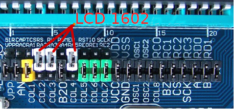 When using the 12864 LCD module or TFT colour screen module, in addition to the connection area ( bottom ) left number 4 , 5 , 7 A total of 3 short-circuit links ( white short-circuit links in the figure below ) are moved to the top to become RA2-RS , RA3-RW , RA5-EN , It must also be (lower) left connected region 3 short-circuiting a number of links (blue in the figure shorting link) to move upward,
Become RA1-TCS: 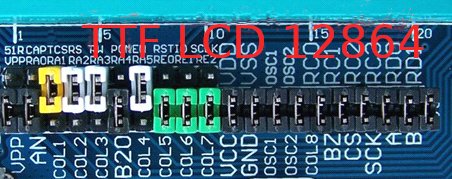 If you do not use the 1602LCD module, 12864 LCD module or TFT colour screen module , please be sure to make sure the position of the short-circuit link is restored to the factory position , that is, the number of the connection area ( bottom ) is 3 , 4 , 5 , and 7 short.
The link ( white, blue shorting link in the figure below ) moves to the bottom and becomes RA2-COL2 , RA3-COL3 .
RA5-COL4 , RA1-COL1: 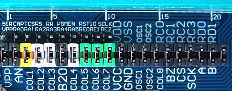 When using the DS1302 real-time clock, set the connection zone (lower) from left 8, 9, 10 of the link 3 shorting
( The green short link in the figure below ) moves to the top and becomes RE0-RST , RE1-IO , RE2-SCLK; 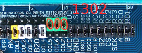 If you do not use the real-time clock DS1302, be sure to restore the above three short-circuit link positions to the factory position.
That is the connection zone (lower) from left 8, 9, 10 of the link 3 shorted (short-circuit under the link in green)
Move to the bottom to become RE0-COL5 , RE1-COL6 , RE2-COL7; Power input mode selection
*1 , the development board is powered by USB2 (when J2 is connected to 1-2 position) 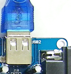
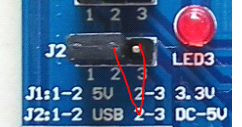 *2 , the development board is powered by an external power supply (when J2 is connected to 2-3 position)
 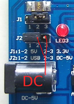 Onboard PICKIT2 online programming simulator
Note: Software installation and how to use PICKIT2 for program burning and simulation, please read other related Tutorial.
The onboard PICKIT2 is an in-circuit programming simulator for PIC microcontrollers. It is actually a programmer. with Such a device emulator combo, not only can program to hundreds of PIC microcontrollers And still Can simulate hundreds of PIC microcontrollers online, the specific supported chip models can see the following columns table.
Not only can it support the programming and simulation of 5V type PIC microcontroller, but also can support 3.3V class type PIC Programming and simulation of the microcontroller, this does not require any prior setup, the onboard PICKIT2 itself has this kind of ability.
The USB1 port is the USB interface of the onboard PICKIT2. To use the onboard PICKIT2, a USB must be used.
The cable connects the USB1 port to the USB of the computer. 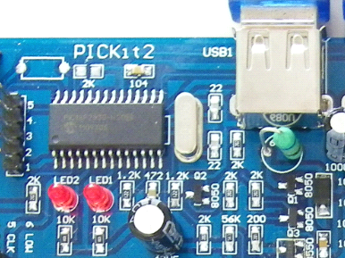 Labelled "LED1" mark corresponding LED board PICKIT2 busy indicator PICKIT2 when idle it is not lit, but it will flash when PICKIT2 is working (such as during programming and emulation).
P22 is the ICSP interface of the onboard PICKIT2 , if you want to carry out the PIC microcontroller on the development board.
Cheng Programming and simulation sequence, from left to right set P22 socket 1, 4, 5 three shorting link (VPP, PGD, PGC) Installed , as shown below : 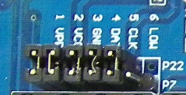 The onboard PICKIT2 not only supports program burning and simulation of the PIC microcontroller on this development board, but also supports hold Program burning and simulation on other development boards or application boards made by users themselves. At this time, remove the P22 socket.
Up All short-circuit links, then in the upper row of the P22 socket (that is, the side marked with PICKIT2, plug in type B 6 core Line (the one with flat heads on both sides), the other end of the B -type 6- core cable and other development boards or user-made application Board ICSP interface.
Switching between 8*8LED dot matrix tube module and 8-digit digital tube display module
Some data lines are shared between the "dot tube module" and the " digital tube module ". With the "8 * 8LED dot matrix module",set S4 all four toggle "ON", S2 all appropriated "OFF": 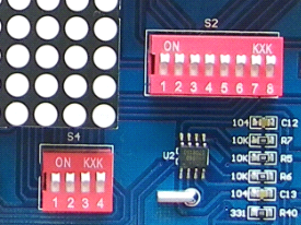 When the "8 -digit digital tube display module " works , please turn all four S4 to "OFF", and all S2 will be selected to.
"ON":
1602, 12864 LCD contrast adjustment
By adjusting the trimmer potentiometer RP2, the contrast adjustment of the 1602 and 12864 LCD screens can be realized. If you have purchased our 1602 LCD screen, it will have adjusted in advance. Under normal circumstances, users do not need to adjust.
If The LCD screen has no display or other 1602 or 12864, the user can adjust the test and adjust Current by Carefully & slowly adjusting RP2. 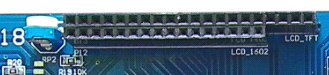 Factory default settings for jumpers
The factory default settings for the experiment board jumper are shown in the figure below :
Module connection area (top) 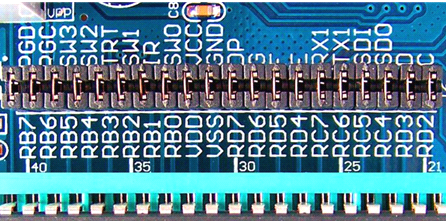 Module connection area ( below )
 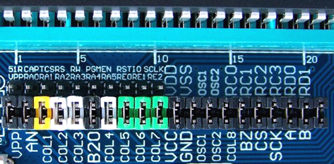 System reset
1, PIC microcontroller reset
When the board is connected to the test board or an external circuit debugger PICKIT2 programmer, by a system reset MPLAB IDE Software control, the reset button (SW-RST) on the experiment board will be invalid.
The following in MPLAB IDE Compiler, the debugger has two modes :
MPLAB IDE when a user uses the programming mode, programming (also called programmed) After completion, breadboard it.
In the stop running state, click the release from reset command on the programmer menu.
Will enter Operating status. If the user wants to reset the experiment board, the operation is to first click on the programmer menu.
Hold in The reset command, after the release from reset, it completes a reset.
When the user uses the debugger mode in MPLAB IDE, after programming (also called programming) is completed, click on it. Debugger reset command in the menu, i.e., a complete reset. The experiment board is connected to the onboard PICKIT2 or an external in-circuit debug programmer, usually in the development phase.
When the onboard PICKIT2 is disconnected or the development board is not connected to the external in-circuit debug programmer (unplug the P22 socket) left Numbers 1,4,5,6 [VPP,PGD,PGC,PGM] four short-circuit links can be disconnected from PICKIT2), system complex Bit by the reset button (SW-RST) on the experiment board is controlled. Press the reset button to complete a reset. Onboard PICKIT2 the disconnect or development board is not connected to the external in-circuit debug programmer and usually occurs during the actual application phase.
MCU installation direction
Pin 1 of the MCU is close to the handle of the green zero-pull insertion socket (ZIF socket), as shown below: 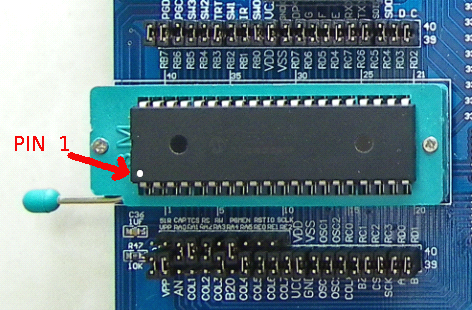 Main component mounting direction
1, DS18B20 chip installation direction
DS18B20 chip is inserted in the socket boards P1, if inserted in the wrong direction, the chip WILL BE DAMAGED. When using, please be careful when you insert the DS18B20 chip into the development board socket P1 in the correct direction: DS18B20 The chip Text faces the outer edge of the development board, as shown below : 2, 1602 LCD installation direction
The installation direction is as follows:
In addition, a very small number of 1602 LCD screen pins on the market are reversed. If this is the case, when installing,
the direction is to be in reverse. It is recommended to purchase our 1602 LCD screen.  3, SD card installation method and direction
When the SD card is installed, it should be face up, and the upward direction arrow is facing forward, gently push it into the SD card holder. Push fully in. To exit the TF card, gently pull out the SD card with your fingers. 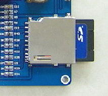 4, stepper motor plug installation direction.
The stepping motor is inserted into the plug socket boards P13, the top plug and receptacle aligned, lower the empty socket 1 pin, as shown below: 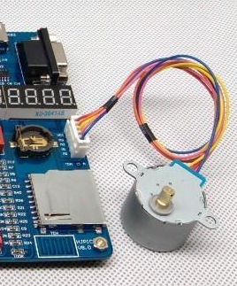 D.C. Motor connections shown below:
 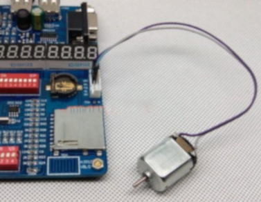 5, TFT colour screen installation
TFT component and HL-K18 development board connection Reminder: All hardware operations must be performed in the power-off state!
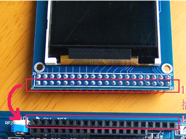
Pins 1-20 of TFT assembly(TFT against the outer edge of the row of the PCB assembly pins) into HL-K18 P11 development board socket. Pay attention to pin 1 of the TFT and insert correctly (with the PCB assembly of the TFT Label) and a pin 1 of HL-K18 development board P11 base is (the development board P11 HL-K18 socket has a small triangle marked on it)aligned. Be careful not to insert it into the P12 socket: Move the four short-circuit links at TCS,RS, RW,and EN in the connection area of the HL-K18 development board to the above position,other shorting links remain in the factory position: 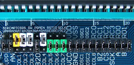 Reminder: TFT assembly pins 1-20 are to be inserted into the socket holder of the development board P11 in the correct position and the system Power must be 3.3V. Please double-check before applying power, otherwise it will cause the LCD screen to burn out! Due to being inserted upside down. Insertion errors & power supply errors are not covered by the warranty ! In order to facilitate the user to write the programs for TFT, the following relationship between the pin connections of the TFT display component and the connection of the microcontroller are given.
A detailed introduction: 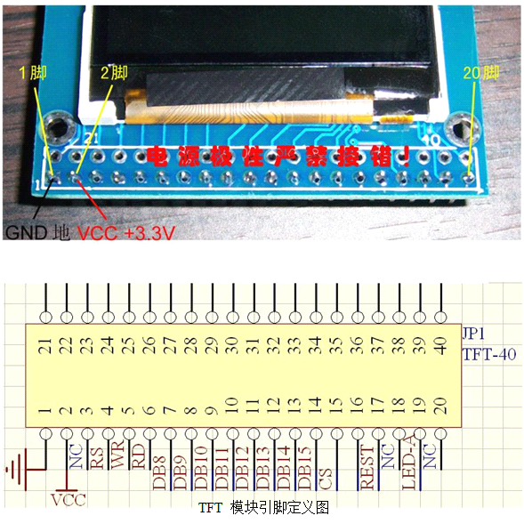
 Note on the onboard PICKIT2 during simulation :
PICKIT2 3 breakpoints can be set up, when all the three breakpoints set, "Step Over" command Order or The button will be greyed out . At this time, only the " single step " command or button is available . If you want to use " single "
Step jump After the " command or button , please set only 2 or 1 breakpoint or no breakpoint. Please also pay attention to PICKIT2 Breakpoint slip Dynamic phenomenon (see "PICkit2 programmer Debugger User's Guide .pdf"), when the program came to a stop at the breakpoint Time , The instruction at the breakpoint has actually been executed.
About low voltage programming : PIC microcontrollers generally use 13V high voltage programming , so PICKIT2 's 6th pin (PGM) is not required connection While a low pressure configuration programming bits so that bits have not, in general we do not use program substantially low pressure, in case Be sure to use low-voltage programming, a set PICKIT2 sixth pin (PGM) short link is mounted, and then Restricted area ( below ) The PGM pin and the PGM pin directly connected to the pin are connected by DuPont line , if the single piece is used Machine is 16F877A, 18F4520, 18F4620, 18F4550 and and their pin-compatible PIC microcontrollers also Is to pick up Split area (bottom) and PGM pin connection region (bottom) RB5 pin connected by Dupont line, configure In the position The low voltage programming bit should be enabled. How to improve the stability of the onboard PICKIT2 under extreme conditions ? During the experiment, especially during high-power experiments (such as a stepper motor test time), occasional Red prompt , this is normal , reset button in the toolbar or re-plug the USB cable (PICKIT2 Free to plug USB cable, without prior deselect development tools) can be restored to normal. In order to improve the stability of the onboard PICKIT2 under extreme conditions , it is recommended to use the development board by USB2.
Power supply or an external power supply mode, because the two power supply, does not change a large current violently resulting in PICKIT2 power transmitted to the interference, thereby greatly improving the stability of PICKIT2. Highlights: If you want the program to run automatically, be sure to disconnect the jumper between P7 P22, and generally Down (1 VPP) is fine .
Here are the prices for the various packages offered to learners :
A. K18-A standard package (USB programming + USB hardware simulation + video tutorial ): With a matching video tutorial - "Teach you to learn PIC microcontroller" video tutorial. With the supporting graphic tutorial - " PIC microcontroller C language tutorial e-book" please click here to view. A high-quality zero-plug force socket suitable for 6-40- pin single-chip microcomputer is selected , which can be easily replaced with various kinds.
The class of single-chip microcomputer , the main crystal oscillator uses a high-quality socket , can be freely replaced with crystal oscillator of various frequencies , can USB program programming ( programming ) and USB hardware emulation ( tuning ) for hundreds of PIC microcontrollers Try ) .
Note : The pictures are for reference only , and the actual shipping list below is subject to change !
National unified price : 288 yuan
Shipping list :
1 , K18 development board
2 , 8X8 dot matrix , has been installed on the learning board.
3 , LCD1602 one.
4, an integrated simulator PICKIT2 programming, note: by sending the KIT2 welded in developing K18
On the board.
5 , 1 infrared remote control .
6 , 2 USB power supply lines .
7, line a 9-pin serial port (if your computer has no serial port, please contact the treasurer plus 8 dollars to replace
Into the USB serial cable)
8, 18B20 temperature sensor 1 in real time (real-time to do testing laboratory temperature)
9: 1 set of short-circuit proof copper posts ( 4 matching nuts )
10: Dupont Line 2 (treasurer had not sent you to do other experiments later inevitably have to spend)
11: A number of jumper links ( will be installed on the learning board before shipment )
12, DVD optical disc 1 (CD-ROM content: K18 development board function set + manual + principle
Figure +20 supporting routines + onboard device reference manual + MPLAB IDE integrated development software,
Companion graphic tutorial ( " PIC microcontroller C language tutorial" e-book ) with all routines
Supporting video tutorial 1 Huijing PIC Getting Started Video
Supporting video tutorial 2 "Teach you to learn PIC microcontroller" video tutorial
Extra gift :
C18 official version of the C language learning software video tutorials wonderful set of C language tutorial part 1 A complete set of PIC microcontroller programs B. K18-B Deluxe Package (USB USB programming + USB +USB hardware emulation + + LCD + + double video tutorial ) :
With a matching video tutorial - "Teach you to learn PIC microcontroller" video tutorial.
With the supporting graphic tutorial - " PIC microcontroller C language tutorial e-book" please click here to view.
A high-quality zero-plug force socket suitable for 6-40- pin single-chip microcomputer is selected , which can be easily replaced with various kinds.
The class of single-chip microcomputer , the main crystal oscillator uses a high-quality socket , can be freely replaced with crystal oscillator of various frequencies , can USB program programming ( programming ) and USB hardware emulation ( tuning ) for hundreds of PIC microcontrollers Try ) .
This package is suitable for beginners and professional users who dream of becoming a master. Includes most optional Member, board PICKIT2, can be USB has been programmed (e.g. for hundreds of PIC microcontrollers Cheng ) and USB hardware emulation ( debug ), with dual LCD and dual video tutorials , can complete all Basic experiments and TFT experiments.
National unified price : 368 yuan
Shipping list :
1: HL-K8 PIC development motherboard 1 set ( integrated original kit2 emulator )
2: LCD1602 LCD 1 block ( blue screen shows white )
3: 8X8 matrix 1
4: an infrared remote control (distribution of a button battery)
5: 1 stepper motor
6: 5V DC 1 (with Plug)
7: 18B20 a real-time temperature sensor
8: 1 Optical speed sensor
9: PIC18F4520 microcontroller 1 block
10: Crystal four different models (of which a shipment of money inserted on the board)
11: Quality lengthened DuPont line 20
12: 9-pin serial cable directly connected to a (computer when no serial port, please let more dispensers plus 8 yuan
Switch to USB to serial cable delivery )
13: high-quality magnetic tape shielded USB cable + 2
14: Several jumper links ( on the loading board before shipment , there are usually more spares )
15: Supporting a teaching CD DVD (on-board resources include rich routines, circuit diagrams, video
Tutorials , as well as detailed study materials, e-books, etc. )
16: Deluxe aluminium alloy development box 1 set ( large , all accessories can be installed at the same time , value
50 yuan )
17, DVD optical disc 1 (CD-ROM content: K18 development board function set + manual + principle
Figure +20 supporting routines + onboard device reference manual + MPLAB IDE integrated development software,
Companion graphic tutorial ( " PIC microcontroller C language tutorial" e-book ) with all routines
Supporting video tutorial 1 "Huijing PIC Getting Started Video"
Supporting video tutorial 2 "Teach you to learn PIC microcontroller" video tutorial
Extra gift :
C18 official version of the C language learning software video tutorials wonderful set of C language tutorial part 1
A complete set of PIC microcontroller programs
Huijing Electronic Network : WWW.HLMCU.COM
Http://shop37031453.taobao.com/
Huijing shop : http://shop37031453.taobao.com/